Skip to content
Reference Designs

Explore various customer deployment scenarios designed for our Stockholm 4 South site, with its flexible design and preparation for high density and liquid cooling. Here, you’ll find three distinct examples, each highlighting a different approach to effective cooling:

EXAMPLES

Each example provides detailed insights and practical layouts to help you envision the best cooling strategy for your needs.

01
Air cooling 1.5 MW
COOLING CAPACITY
1.5 MW air cooling
RACK DESIGN
Up to 44 kW per compute rack
20 kW per management rack
Total Deployment
Four pods with 10 racks each
Total of 40 racks in this example
Power Supply Requirements
Each rack requires two/four 63A 3-phase PDUs
Two 400A busbars above each row of racks

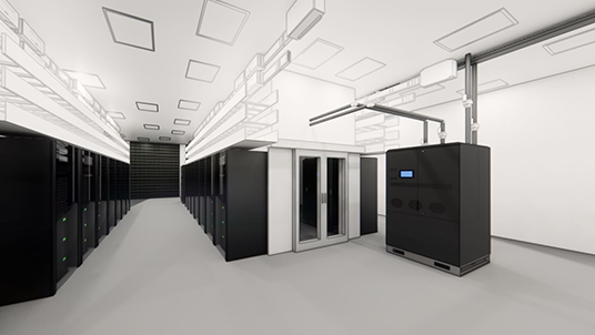
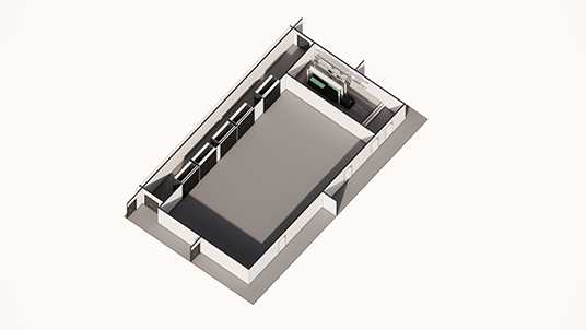
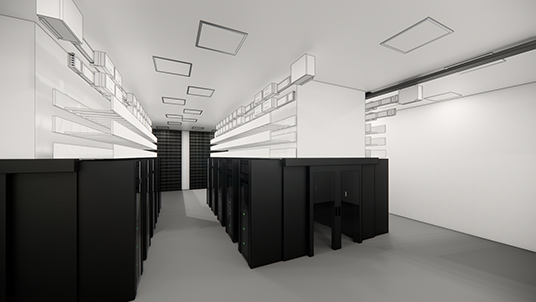
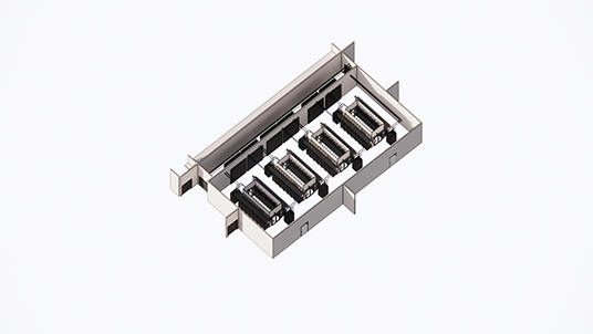
How this deployment could look like in this scenario.

Alternative configurations can be accommodated to meet varying needs, including setups designed to support high-performance computing clusters used in leading-edge AI deployments. Please note that this is just one example; for different deployments or specific setups, we offer flexibility and welcome you to contact us to discuss your needs in more detail.

01
Air cooling 1.5 MW
COOLING CAPACITY
1.5 MW air cooling
RACK DESIGN
40 kW per rack
Total Deployment
Four pods with 10 racks each
Total of 40 racks
Power Supply Requirements
Each rack requires two 63A 3-phase PDUs
Two 400A busbars above each row of racks

How this deployment could look like in this scenario.

Alternative configurations can be accommodated to meet varying needs, including setups designed to support high-performance computing clusters used in leading-edge AI deployments. Please note that this is just one example; for different deployments or specific setups, we offer flexibility and welcome you to contact us to discuss your needs in more detail.

02
Direct-to-Chip Liquid Cooling 3.6 MW
COOLING CAPACITY
Maximised power with direct-to-chip
liquid cooling, totaling 3.6 MW
RACK DESIGN
64 kW per rack
Total Deployment
3.6 MW net server load (NSD)
Approximately 56 racks
Total Consumption
2.8 MW using liquid cooling
840 kW using air cooling, equivalent to 15 kW per rack
Power Supply Requirements
Each liquid-cooled rack requires
two sets of two 63A 3-phase PDUs
Four 630A busbars above each row of racks

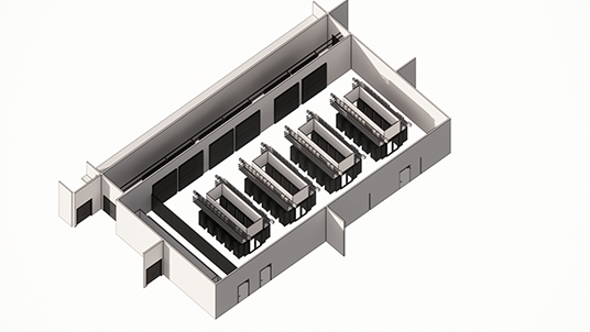
How this deployment could look like in this scenario.

Alternative configurations can be accommodated to meet varying needs, including setups designed to support high-performance computing clusters used in leading-edge AI deployments. Please note that this is just one example; for different deployments or specific setups, we offer flexibility and welcome you to contact us to discuss your needs in more detail.

02
Direct-to-Chip Liquid Cooling 3.6 MW
COOLING CAPACITY
Maximised power with direct-to-chip
liquid cooling, totaling 3.6 MW
RACK DESIGN
64 kW per rack
Total Deployment
3.6 MW net server load (NSD)
Approximately 56 racks
Total Consumption
2.8 MW using liquid cooling
840 kW using air cooling, equivalent to 15 kW per rack
Power Supply Requirements
Each liquid-cooled rack requires
two sets of two 63A 3-phase PDUs
Four 630A busbars above each row of racks

How this deployment could look like in this scenario.
Alternative configurations can be accommodated to meet varying needs, including setups designed to support high-performance computing clusters used in leading-edge AI deployments. Please note that this is just one example; for different deployments or specific setups, we offer flexibility and welcome you to contact us to discuss your needs in more detail.

03
Immersion Cooling System 1 MW
COOLING CAPACITY
1 MW total NSL distributed across
multiple immersion cooling systems
SYSTEM DESIGN
Each immersion system consumes
0.5 MW (4 tanks per system)
1 MW total requires 2 immersion systems
Equivalent to 2.4 kW/U with fully
equipped tanks having 52U each
Power consumption
Air system: 5-10 kW
Remaining hall space can be
used for air cooled systems
Power Supply Requirements
Each immersion-cooled tank requires
two sets of three 63A 3-phase PDUs
Four 400A busbars above each immersion system

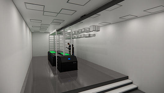
How this deployment could look like in this scenario.
How can we help you?


Back To Top